This project is an automated drink-mixing vending machine designed to sit inside a refrigerator and dispense customized beverages on demand. Powered by an ESP32 microcontroller, it uses multiple small water pumps to move syrups, juices, and soda from separate containers into a cup.
A touchscreen interface built with the LVGL graphics library lets users select drink combinations directly on the device. Once selected, the ESP32 activates the correct pumps for specific durations to dispense ingredients in the right proportions.
The Concept
A compact automated beverage station that lives inside a fridge. Ingredients stay separate and cold until mixed on demand — resulting in a freshly blended drink every time. The system combines an embedded control unit, liquid pumps, and a touchscreen for a seamless, customizable experience.
| Component | Purpose |
|---|---|
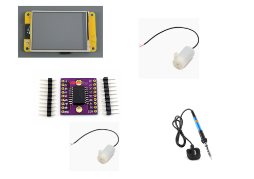
| ESP32 Microcontroller | Central control — manages pumps and touchscreen. |
| Water Pumps | Dispense liquids from containers into the mixing area. |
| Ingredient Containers | Store syrups, juices, and soda separately. |
| Touchscreen (LVGL) | User interface — browse drinks and view mixing progress. |
Circuit Layout
LVGL Screen → ESP32S3
Jumper Wires → ULN2803A → Water Pump
Updates
-
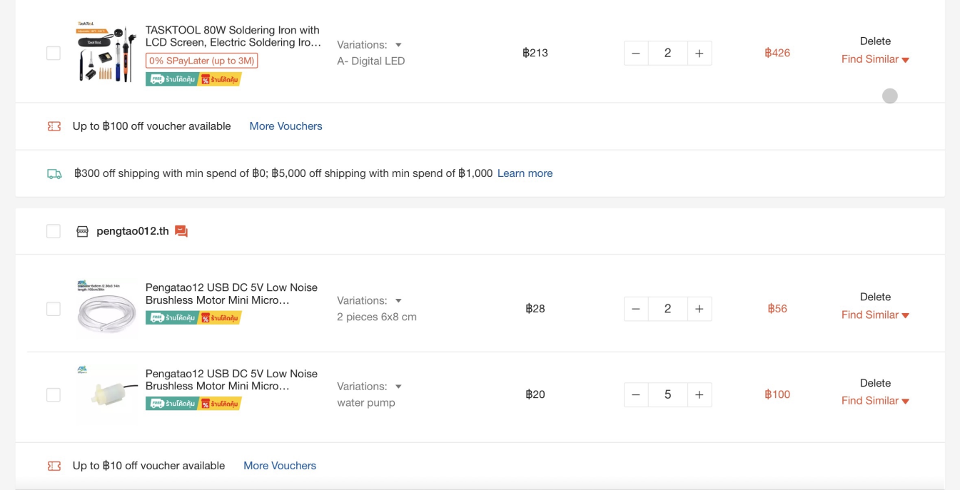
Update 1 Buying the Materials — 28/2/26
Added all necessary materials to the cart. Awaiting funding to proceed with the build.
-
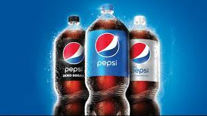
Update 2 Enlisting Donors — 8/3/26
Convinced Naru to buy Caleb a Pepsi — in the future he'll fund the soda supply for the machine.
-
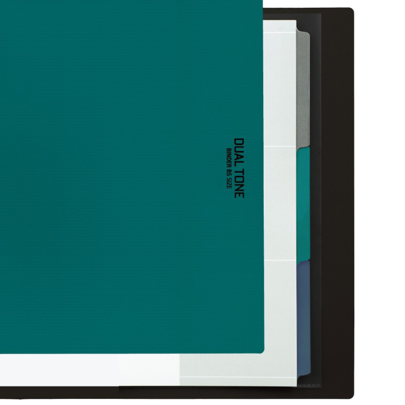
Update 3 Buying Folders & Saving Funds
-
Update 4 To Be Continued
Update coming soon!

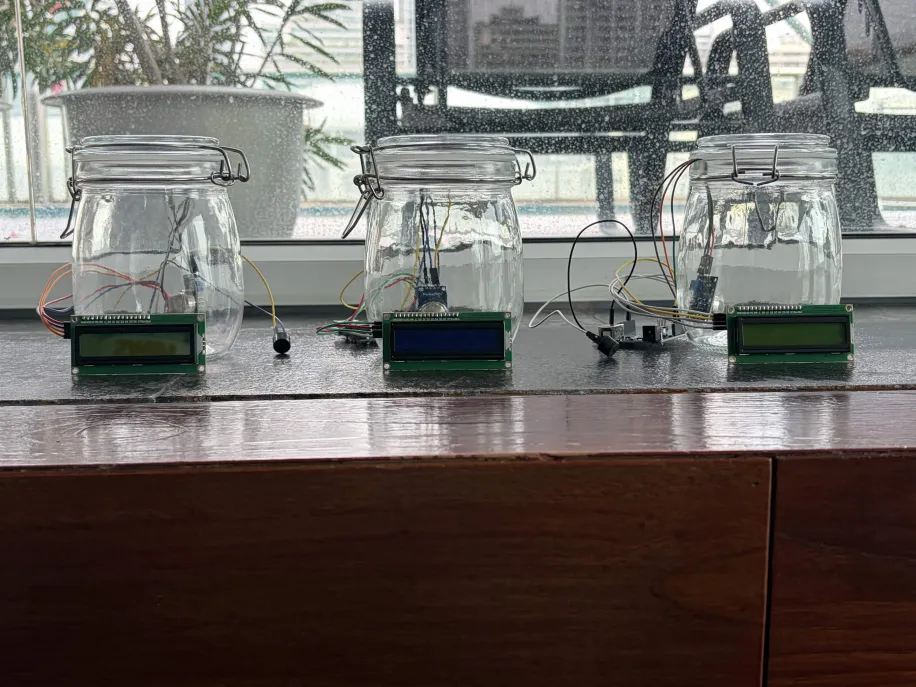
Our project explores how human activity has degraded air quality over time. We built a device that detects and measures CO₂ and other common pollutants (ammonia, alcohol vapors, benzene, smoke) — alerting users when readings rise dangerously high — and used it to illustrate real-world environmental changes across decades.
The Concept
Our detector senses CO₂ and other common indoor pollutants (ammonia, alcohol, benzene, smoke) in a given area and displays readings in real time. It helps people visualize and understand the invisible impact of pollution — making the abstract measurable.
Parts List
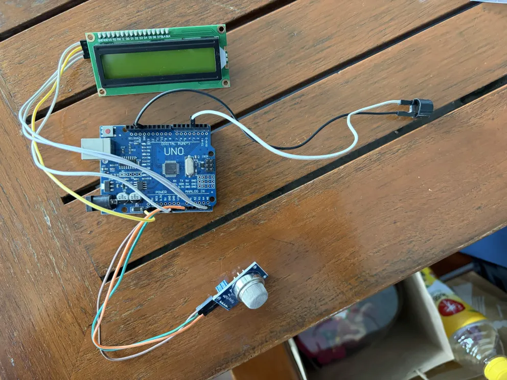
- Arduino Nano
- MQ135 Flying Fish Module
- Jumper Wires
- I2C Display
| Part | Purpose |
|---|---|
| Arduino Nano | Controls the system and processes sensor data. |
| MQ135 Flying Fish Module | Detects CO₂, ammonia, alcohol, benzene, and smoke. |
| Jumper Wires | Connects components together. |
| I2C Display | Shows real-time air quality readings. |
Circuit Layout
MQ135 → Arduino Nano
Jumper Wires → I2C Module → I2C Display
Laptop → System (programming)
Updates
-
Update 1 Buying the Materials
Mostly sourced. One MQ135 sensor broke during delivery and had to be replaced.
-
Update 2 Assembling the Prototype
Built the first version on a breadboard using YouTube reference code, modified to fit our use case. Tested for the first time at 9:00 PM — it worked.
-
Update 3 Team Meetup
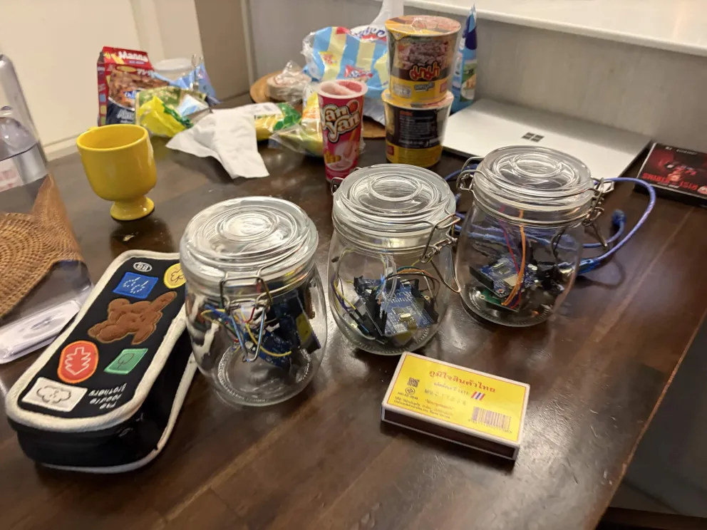
Brought all materials to a teammate's house, assembled the device, and confirmed it worked on another machine. Took high-quality photos for the futureboard.
-
Update 4 Final Device
Assembled the complete futureboard and final project submission.
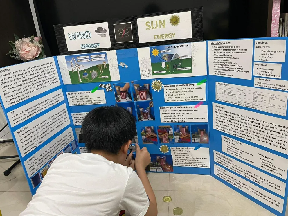
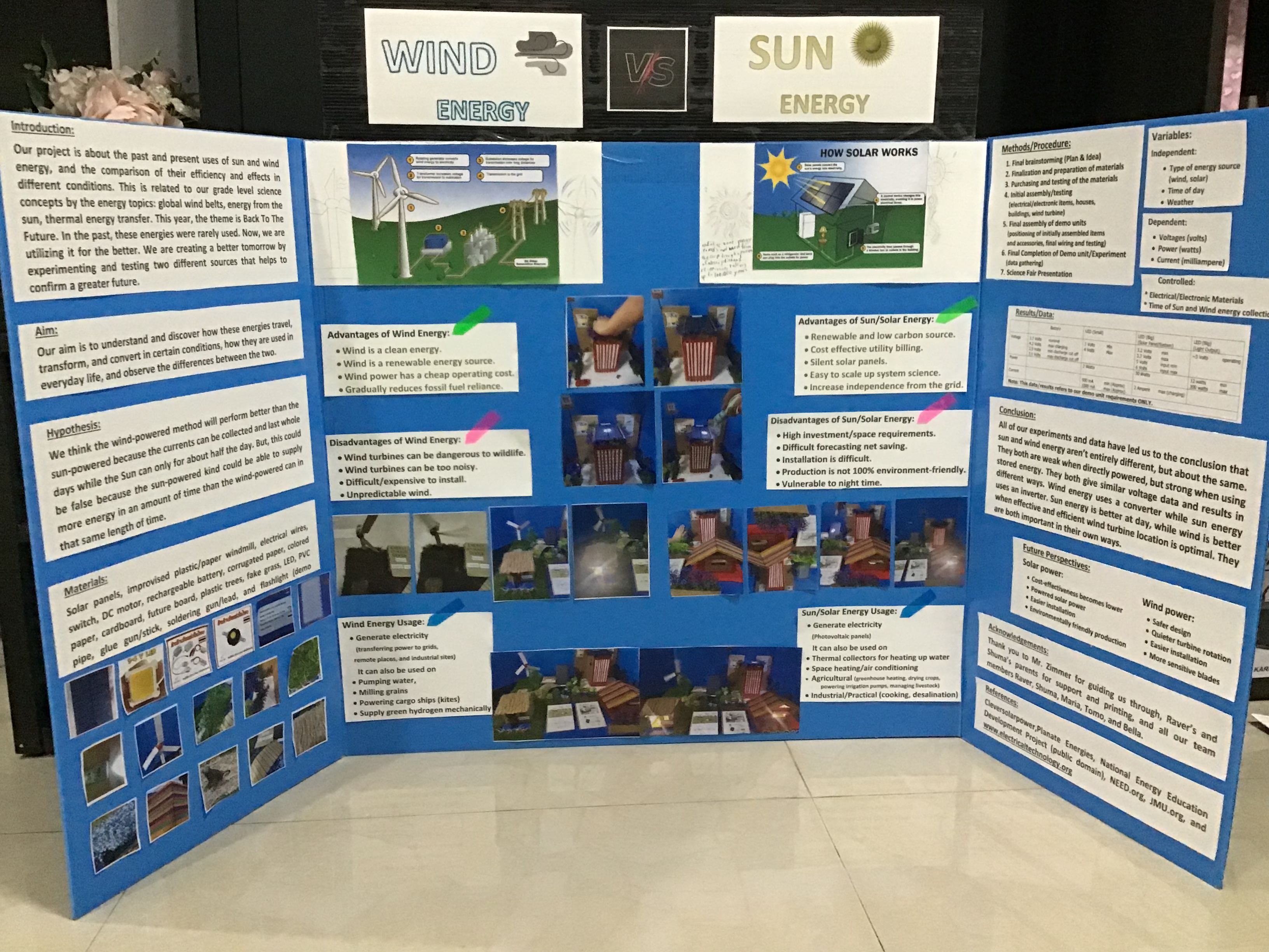
Back when fossil fuels dominated, clean energy alternatives were rarely compared head-to-head. We designed an experiment to power LEDs using both a wind turbine and a solar panel, measuring voltage, current, and efficiency under controlled conditions. The result: both sources performed similarly.
The Concept
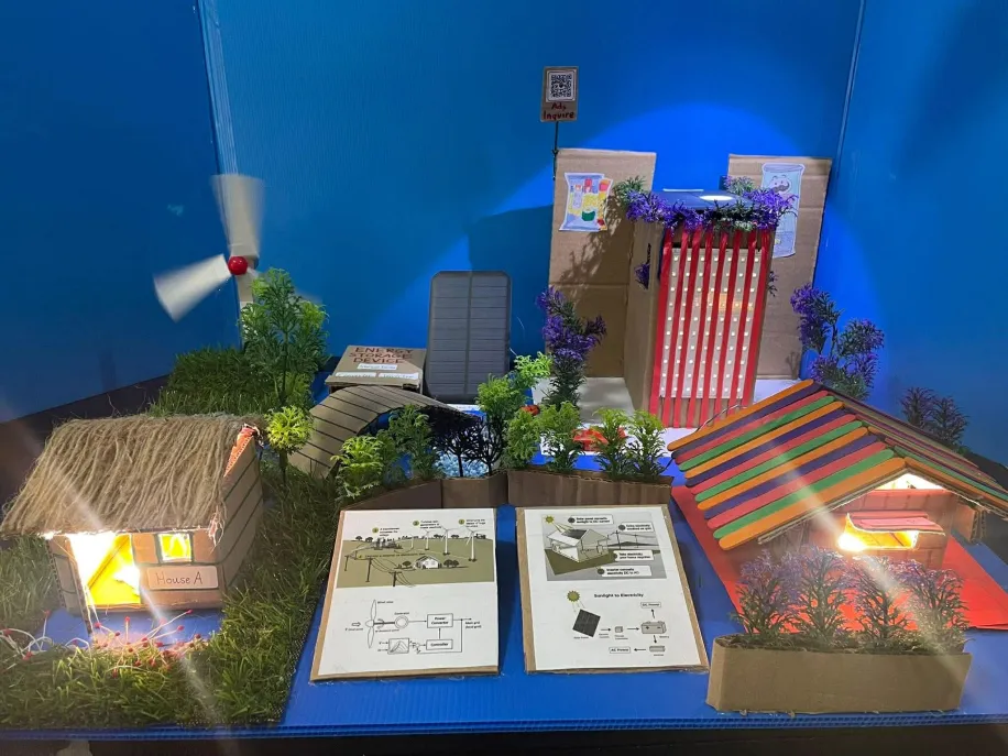
We built two LED circuits — one powered via a wind turbine, one via solar panels — and measured output across multiple trials. The goal was to determine which is better suited for different environmental conditions, helping inform future energy decisions.
Conclusion
Both wind and solar produced similar electrical outputs under our test conditions. Each system responded to its respective input — stronger gusts boosted the turbine, more sunlight boosted the panel. While their generation mechanisms differ, the measurable outputs were comparable, making both reliable and viable for renewable energy applications.
| Part | Purpose |
|---|---|
| Solar Panels | Secondary generator of energy |
| Plastic Wind Turbine | Primary generator of energy |
| Electrical Wires & Switch | Connects components together |
| Decoration | Makes the project aesthetically presentable |
Updates
-
Update 1 Buying the Materials — 15/1/26
Most materials were already at home. Ordered the remaining electrical components online.
-
Update 2 Changing Ideas — 5/2/26
Initial concept was too broad. Narrowed focus to a direct comparison between wind and solar — a cleaner, testable question.
-
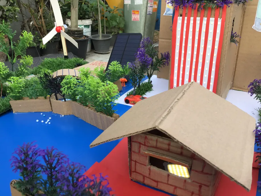
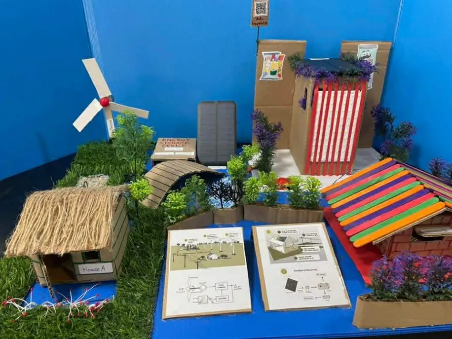
Update 3 Assembling the Presentation
Built miniature houses and a skyscraper, wired LEDs to both the solar panel and wind turbine — they worked on the first try. Decorated it to look like a small city, then finished the trifold futureboard.
-
Update 4 Science Fair — 20/2/26
Presented at the Science Fair. Despite a mid-demo battery shortage in the wind turbine, the team recovered well and placed 2nd in the grade level.
Globally, roughly 43 million people are blind and over 2.2 billion live with some form of vision impairment. Many rely on canes, guide dogs, or expensive commercial devices. But what if a small wearable computer could simply describe the world through sound? That question became SoundView.
The Concept
SoundView detects objects in the user's environment using a camera, processes that input with a microcontroller, and delivers real-time audio feedback through a speaker. Instead of seeing obstacles, the user hears them.
The glasses combine
- Microcontroller processing
- Camera input
- Audio output
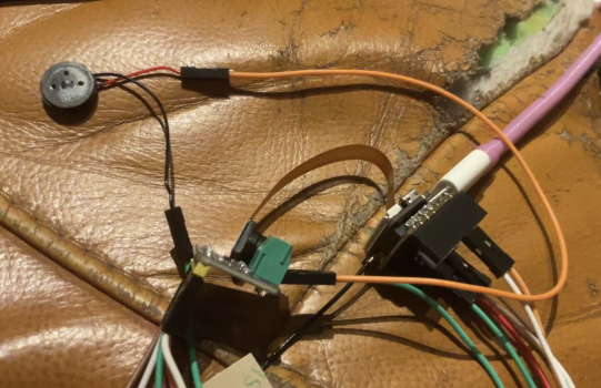
The first prototype was minimal — a glasses frame, microcontroller board, sensor module, and wired audio output. It looked rough, but it worked.
| Part | Purpose |
|---|---|
| ESP32-S3 Sense | Main microcontroller — onboard camera + microphone, drives everything over WiFi |
| Max98357A Speaker Driver | I2S class-D amplifier that converts digital audio to speaker output |
| 13MM Speaker | Plays the AI's spoken response near the user's ear |
| Jumper Wires | Connects the speaker driver to the ESP32-S3 Sense |
| Frame | Wearable mount |
System Design
The Loop
Voice/Camera → ESP32-S3 Sense → WiFi → OpenAI Vision API → Text → TTS → Speaker
- ESP32-S3 Sense records voice input via its onboard microphone and captures an image via its onboard camera
- Both are sent to OpenAI's Vision API over WiFi for scene analysis
- The AI's text response is converted to audio and played through the 13MM speaker via the Max98357A driver
Example Output
"The image depicts a young male with short dark hair wearing a striped jacket over a light shirt who appears to be laying down. There is also a painting behind the person."
Circuit Layout
Onboard Camera + Mic → ESP32-S3 Sense
ESP32-S3 Sense (I2S) → Max98357A → 13MM Speaker
ESP32-S3 Sense (WiFi) → OpenAI Vision API → Text Response
Test Results
We ran three controlled tests comparing SoundView's description of a scene against a human control's description. The hypothesis: our glasses will have the same descriptional accuracy as a human. Result: 3/3 scenes recognized, with one minor over-statement (kitchen utensils) and one object misidentification (microwave vs. air fryer).
Verdict: Quite accurate — the only inaccuracy was calling the surrounding items "kitchen utensils."
Verdict: This description is spot on. No comment needed.
Verdict: Glasses called an air fryer a "microwave" and imagined trash that wasn't there — but caught the overall atmosphere of the environment.
Biggest Challenges
- Weight — electronics quickly make glasses uncomfortable; future builds will use smaller boards.
- Power — wearable devices need long battery life; low-power modes are essential.
Possible Improvements
- Battery optimization using low-power components and sleep modes.
- Hardware miniaturization with smaller MCUs and integrated circuits.
- Software efficiency — optimized code reduces processing time and power draw.